Absolute GPS to better than one meter - Page 3
3. Specific Corrections
Ionosphere (2-frequency model)
The ionosphere correction is often only a few meters. But in extreme cases near solar maximum, it might reach 50 meters in the zenith, or three times that near the horizon. It is generally five times larger during the day than at night, four times larger in November than in July, and four times larger at solar maximum than at solar minimum in the 11.1-year sunspot cycle.
| f0 | 10.23 MHz |
| f1 | 154 f0 = 1575.42 MHz |
| f2 | 120 f0 = 1227.60 MHz |
Table 6. GPS fundamental and carrier frequencies.
The standard two-frequency corrections for ionospheric delay may be found in many references; for example, (Wells, 1987) or (Klobuchar, 1996). It is presumed that we have measured the pseudo-range PR simultaneously at two different L-band carrier frequencies, L1 = f1 and L2 = f2. These frequencies are multiples of the fundamental frequency f0. Numerical values for the GPS system may be found in Table 6. Note that the Russian GLONASS system uses different frequencies.
Let PR1 and PR2 be the two simultaneous measures of the pseudo-range at L1 and L2, respectively; and let ADR1 and ADR2 be the corresponding measures of the accumulated delta range. Then the corrections for ionospheric delay are given by:
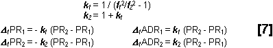
For GPS, the numerical values of the constants are k1 = 1.545728 and k2 = 2.545728. After these corrections are applied, the two observed pseudo-ranges will be equal. Note that this is the only correction that affects pseudo-range and accumulated delta range differently. This is because the phase velocity of electromagnetic waves through a resisting medium exceeds the speed of light.
Troposphere
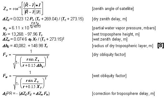
Corrections for tropospheric delay are generally about two meters in the zenith, but can be an order of magnitude larger at 10° above the horizon. The correction is in two parts, one for the dry atmosphere and one for the wet component. The latter is usually only about 10% of the total correction, but has considerably more uncertainty because it depends on the water content of the air all along the path, not just at the ground station. For greatest accuracy, barometric pressure, temperature, and dew point data are all required. Because these are no longer measured at the Air Force monitor stations, we obtained this data from the National Oceanic and Atmospheric Administration’s National Weather Service at the National Meteorological Center.
Troposphere models may be found in several references, e.g. (Spilker, 1996) and (Navstar, 1978). We take as inputs to the model the following quantities: r = distance of receiver from Earth center in meters; Ps = pressure at receiver in kilopascals; Tc = temperature at receiver in degrees Celsius; Td = dew point at receiver in degrees Celsius; is the geocentric satellite position vector, and is the geocentric receiver position vector. Then the correction to the observed pseudo-range is:
Orbital relativity (due to eccentricity)
In Einstein’s theory of general relativity (GR), gravitational potential changes the rate of a clock by the factor (1 - GMÅ / Rc2) , where G = gravitational constant, MÅ = mass of Earth , R = distance of clock from center of Earth, and c = speed of light. A similar but much smaller effect caused by the change in gravitational potential of the Sun across the orbit of a GPS satellite will be discussed in the analysis section. For now, this will be neglected. Adopting a mean value for R = 26,560,000 m for all GPS satellites and taking the other constants from Table 7, their rate slowing due to Earth’s gravitational potential is 1.67x10⁻¹⁰ relative to clocks at infinity. The rate slowing due to Earth’s gravitational potential for a clock located on the Earth’s geoid, say, at the north pole where R = 6,357,000 m, is 6.98x10⁻¹⁰ relative to clocks at infinity. Since clocks on the Earth’s geoid are used to define the international standard second of time, GPS satellite clocks run fast relative to ground clocks by the difference of these two factors, 5.31x10⁻¹⁰. So satellite atomic clocks are rate-adjusted downward before launch by that factor, resulting in clocks in orbit that tick at the same average rate as ground clocks. Because this compensation is complete for the mean altitude of GPS satellites, the GR effect on the GPS system can essentially be ignored.
| Parameter | Value |
| c | 299,792,458 m s-1 |
| GMÅ | 3.986008x10¹⁴ m3 s-2 |
| GM2 | 4.902798x10¹² m3 s-2 |
| GM3 | 1.327124x10²⁰ m3 s-2 |
| h2 | 0.6090 |
| l2 | 0.0852 |
Table 7. Numerical values of physical constants.
The only exception is a small correction, always less than 5 m, for periodic variations in satellite clock rates caused by the small orbital eccentricity of the satellites. This may be computed to sufficient accuracy by correcting the satellite clock readings by the amount+2290 e sin l in ns, where the eccentricity e may be taken, and mean anomaly l computed, from Table 2. This translates into the following correction to the observed pseudo-range in meters:
D3PR= -686.5 esin l[9]
In Einstein’s theory of special relativity (SR), the relative velocity between two clocks changes their relative rates such that each sees the other tick slower; the distance between them appears to contract; and the two effects (time dilation and space contraction) combine to leave the apparent speed of light c unchanged as measured by observers at either clock. These changes are expressed by the vector form of the Lorentz transformations (Robertson & Noonan, 1968):
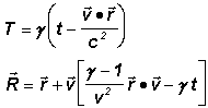
where is the relative velocity vector and v is its magnitude, (t, ) are time and x, y, z coordinates in the receiver co-moving frame, (T, ) are time and X, Y, Z coordinates in the satellite co-moving frame, and the space contraction / time dilation factor g = 1 / Ö (1 - v2/c2).
The largest velocities we normally need to consider in the GPS system are those of a typical satellite with respect to the center of the Earth, about 3,900 m/s, for which v/c is 1.3x10⁻⁵. This makes the g factor exceed unity by about 0.84x10⁻¹⁰. Hence, space contraction is no more than 2.2 mm and can always be neglected for our purposes here. Likewise, since a typical flight time for a signal from satellite to ground is about 80 ms, time dilation during that downlink time is about 67 picoseconds (ps), also negligible here. Of course, the slowing effect on clock rates is not negligible because it eventually builds up a significant time difference. However, just as for the gravitational potential effect, GPS satellite clock rates are pre-adjusted upward before launch to compensate for the average value of this velocity effect, resulting in orbiting clocks that are seen to tick at the same average rate as ground clocks. The remaining small changes in clock rates due to orbital eccentricity causing the satellite to speed up and slow down contribute clock corrections that are always less than 5 m for the 1993 satellite constellation. We take this correction (equation [9] above) into account in our calculations.
So we can simplify the Lorentz transformations considerably by taking g = 1 in the small terms, and g = (1 + ½ v2/c2) in the terms factored by t:
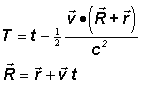
Note especially the appearance of the factor ½. In derivations that simply set g = 1, this factor is lost, and the resulting equation sets are no longer symmetric between frames. In the GPS system, the first of these equations is always further simplified to T = t, neglecting the so-called "relativity of simultaneity" effect, which is the term factored by ½. This is justified by arguing that all clocks will be synchronized to the underlying ECI coordinate frame instead of to their own frame. This is also necessary because to do otherwise would lead to contradictory requirements on the settings of satellite clocks relative to ground clocks.
For example, consider an arbitrary satellite, a receiver fixed at the north pole, and a set of additional receivers moving in various directions at various speeds, yet each arriving at the north pole at a common instant. Then at that common instant each receiver would place a different requirement on the difference T - t since differs for each. These differences are of order 10-20 m, and are therefore appreciable. As an immediate consequence of neglecting the relativity of simultaneity term when comparing receiver and satellite clocks, the satellite clocks are generally not Einstein-synchronized with respect to the ECF or the receiver co-moving frames. We will comment further on the implications of this in the analysis section of this paper.
Solid Earth tides delays
We have used the algorithms of (McCarthy, 1992) to compute deformations of the solid Earth under the stress of lunar and solar tides. These corrections have a maximum effect of about 0.3 meters in the station coordinates for the cases considered here. Only McCarthy’s equation (6) is needed for our analysis. If it were our intention to compare the station coordinates we derive with coordinates derived from data types that have applied no Earth-tide model, we would need McCarthy’s equations (8) as well. The correction to the adopted coordinates to include the effect solid Earth tides is:
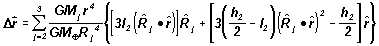
where
D = observed station coordinate vector minus reference station coordinate vector
GM j = product of gravitational constant and mass for the Moon (j = 2) or the Sun (j = 3),
GMÅ = product of gravitational constant and mass for the Earth,
 = unit vector from the geocenter to Moon or Sun and the magnitude of that vector,
 = unit vector from the geocenter to the station and the magnitude of that vector,
h2 = nominal second degree Love number,
l2= nominal Shida number.
Numerical values of the constants may be found in Table 7. Since we should apply this correction to the adopted coordinates, it will affect the computed values of the pseudo-range rather than the observed values.
Simplified models for the vectors to the Moon and Sun, accurate to about 0.3°, were used for solid Earth tide calculation and other low-precision purposes. Both models used time T in Julian centuries from J2000 as input (as defined just prior to equation [3]), and produced ECI coordinates as output.
Solar model
Subscript 3 refers to the Sun. The rotation R1 below is defined in equation [4].
| L3= 280.460° + 36,000.770° T | [solar mean longitude] |
| l3 = 357.528° + 35,999.050° T | [solar mean anomaly] |
| (v3 - l3) = 1.915° sin l3 + 0.020° sin 2 l3 | [solar equation of center] |
| l3 = L3 + (v3 - l3) | [solar true longitude] |
| v3 = l3 + (v3 - l3) | [solar true anomaly] |
| e = 23.439 3° - 0.013 00° T | [obliquity of the ecliptic] |
| e3 = 0.016 708 617 | [solar eccentricity] |
| r3 = 149,597,870 (1 - e 32) / (1 + e 3 cos v 3) | [magnitude of solar radius vector, km] |
| 3 = R1(-e ) {r 3 cos l 3, r 3 sin l 3, 0} | [solar radius vector, ECI coordinates, km] |
Lunar model
Subscript 2 refers to the Moon. The rotation R1 below is defined in equation [4]. e is defined above in the solar model.
| l 2 = 134.927° + 477,198.867° T | [lunar mean anomaly] |
| F2 = 93.272° + 483,202.018° T | [lunar mean argument of latitude] |
| D = 297.850° + 445,267.111° T | [mean elongation of Moon from Sun] |
| W 2 = 125.045° - 1,934.136° T | [lunar longitude of ascending node] |
| l 2 = F2 + W 2 + 22,640" sin l 2 - 4,586" sin (l 2 - 2 D) + 2,370" sin (2 D) | [lunar true longitude] |
| b 2 = 18461" sin F2 + 1,010" sin (l 2 + F2) + 1,000" sin (l 2 - F2) | [lunar latitude] |
| r 2 = 6,378.136 3 (60.362 98 - 3.277 46 cos l 2 - 0.579 94 cos (l 2 - 2 D) - 0.463 57 cos (2 D) | |
| [magnitude of lunar radius vector, km] | |
| 2 = R1(-e ) {r 2 cos l 2 cos b 2, r 2 sin l 2 cos b 2, r 2 sin b 2} | [lunar radius vector, ECI coordinates, km] |
Satellite offsets
The antenna on the satellite is not located at the center of mass. Fortunately, however, it always remains pointed straight downward, so satellite spin does not need to be modeled. And the offset between center of mass and antenna is the same for most satellites (see Table 8). Therefore, with quantities defined as in Equations [8], the offset correction to the observed PR is simply the Table 8 value projected onto the pseudo-range:
| Satellite | Offset |
| SV 35, 36 & 38 | +1.8664 m. |
| all others | +0.9519 m. |
Table 8. Offsets of satellite antenna from satellite center of mass.
4. Sample Calculation
| UT1 | 15h44m51.4815425s |
| GMSTt | 3.633 080 40 rad |
| GMSTr | 3.633 080 40 rad |
| X | +12,318,856.50 m |
| Y | -10,190,204.31 m |
| Z | +21,334,249.68 m |
| X’ | +3,017.55990 m/s |
| Y’ | +2,322.31113 m/s |
| Z’ | -628.77318 m/s |
| x | +6,063,015.09 m |
| y | +1,729,609.43 m |
| z | +960,842.89 m |
| x’ | -126.1 m/s |
| y’ | +442.1 m/s |
| z’ | +000.0 m/s |
Table 9. UT1 time, rotation angle, and ECI coordinates of satellite and monitor station.
To illustrate our calculation procedure with a numerical example, we begin with the ECF state vector of Table 4, which is for SV 32 at GPS time 1993 Aug. 23d 15h 45m 00s = JD 2,449,223.15625 exactly. If we need it for some non-tabular moment, we could obtain that by Lagrangian interpolation. Then we will compare the computed ranges and observed pseudo-ranges from Kwajelain at that epoch. The ECF state vector for the monitor station is from Table 1, where of course the velocity components in the ECF frame for a station fixed on the Earth are all zero. Additional quantities that will be needed for the calculations may be extracted from Table 2 through Table 8.
Our first step will be to rotate both of these state vectors into the ECI frame. For the satellite state vector, we use [2] to get UT1 from the GPS time, then [3] to get GMSTt, the Greenwich Sidereal Time at the time of satellite transmission. For the receiver state vector, the time of reception is found from [6]. Then we use [4] and [5] to rotate from ECF to ECI. The extracted values and results to this point are summarized in Table 9.
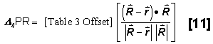
Next, we form the computed PR and ADR from [1], and take the observed PR and ADR at frequencies L1 and L2 from Table 5. It is somewhat arbitrary whether to apply corrections to the observed or computed values. But we will attempt to apply them so as to bring both values as close as possible to the actual geometric distance through space traveled by the signal. Therefore, clock corrections from Table 3 are applied to the observed PR and ADR, as are ionosphere and troposphere delay corrections from [7] and [8] , the orbital relativity correction from [9], and the geometric offset correction from [11]. The solid Earth tide corrections from [10] will be used to correct the computed PR and ADR, since these change the true geometric range.
| r | 24,417,279.25 m |
| eq.10 | 0.00 m |
| calc. | 24,417,279.25 m |
| PRobs | 24,586,975.07 m |
| k-clock | -514,207.33 nsm |
| 32-clk | -51,794.41 ns |
| net | -169,676.60 m |
| D 1PR | -5.66 m |
| D 2PR | -10.75 m |
| D 3PR | -0.62 m |
| D 4PR | +1.00 m |
| obs. | 24,417,281.44 m |
| (O-C) | +2.19 m |
Table 10. Corrections and adjusted values of pseudo-range and accumulated delta range, observed and computed.
The final step is to form the (O-C) from the (Observed PR minus Computed PR). The results of computations for all these corrections and various intermediate quantities are summarized in Table 10. The final residual differs from this (O-C) in that additional corrections to the clocks, station coordinates, and the demodulator delays are derived from the analysis of all observations, as described in the next section.
5. Data Analysis
Reducing our data in this way, we can compute calculated ranges to compare with the observed PR values. The differences (O-C) in the sense of observed minus calculated can then be examined to determine how good our modeling has been. For each solution, we choose to analyze PR or ADR values, or some combination such as the average of the two. If we analyze ADR values, then each uninterrupted span of data during which the ADR value is accumulated requires solving for a single arbitrary additive constant to convert ADR into a pseudo-range-like quantity. Typically, this is one constant per passage of each satellite for each monitor station, or one constant for several hours of 1.5-second data. Because the ADR values need this additive constant, and because of occasional cycle slips corrupting the ADR counts, we prefer to use PR values alone. However, the higher precision of ADR measurements makes them very useful for reducing the scatter in PR measurements over any short arc.
Our second decision before performing an analysis run is what clock corrections to solve for. Typically, we must solve for one arbitrary offset correction and one rate correction for each clock in the system, both for satellite and ground clocks. Of course, one clock must be treated as the "master clock" providing the definitions of epoch and length of the second, or time would be indeterminate. For that purpose we adopt the Colorado Springs (CSOC) monitor station clock as the most closely tied to the U.S. Naval Observatory master clock. So we accept the clock corrections to the CSOC clock in Table 3 as exact, and solve for additional corrections needed to all other clocks.
Existing atomic clocks are not generally expected to remain well-behaved over a four-day time span because their rates are not stable for that long. Therefore we may choose to solve for additional clock corrections – for example, one additional rate correction for each clock each day. Because clock rate instability seemed to become significant in a bit less than a day, and to avoid confusion with 12-hour and 24-hour signals in the data, we adopted one clock rate correction every 16 hours for most of our analyses.
Our next decision is whether to solve for corrections to the adopted coordinates of the monitor stations, or whether to keep those coordinates fixed at their adopted values. For best results, corrections should be solved for, because the adopted coordinates are not as accurate as the precision our solutions can reach. However, sometimes other quantities of interest could become indeterminate if solved for simultaneously with station coordinates.
Each monitor station also has two delay corrections associated with it, mainly caused by cable lengths. The delay is different for the L1 and L2 band signals. These two delay corrections, one for each frequency, are called "demodulator" corrections. These corrections are not guaranteed to remain fixed over time because demodulators and cabling are sometimes changed. But over our four-day span we have assumed that the two corrections per demodulator do remain unchanged. There are potentially twelve odd-numbered demodulators associated with L1 and twelve even-numbered demodulators associated with L2 for each monitor station, totaling 60 pairs over the five monitor stations. However, ten of those pairs were inactive during this time span, leaving 50 pairs of demodulator corrections to be solved for.
We further note that the existence of two unknown demodulator corrections means that the two simultaneous measures of PR for L1 and L2, which we called PR1 and PR2 in Equations [7], may differ by a constant. But this will imitate a delay produced by the ionosphere. So to eliminate indeterminacy in our solutions, we solve instead for one constant bias in PR for each odd-numbered demodulator, except for one odd-numbered demodulator per monitor station for which no correction to PR is allowed. And we solve for one constant bias in (PR2 - PR1) for each even-numbered demodulator, except for one even-numbered demodulator overall for which no correction to (PR2 - PR1) is allowed. We chose the demodulators that seemed to need the smallest corrections in trial solutions as our reference demodulators.
Finally, we determine if there are any special parameters we might wish to solve for to test various theses about the data, and if we wish to use the entire four-day data span or some subset of it. We initially did not provide for corrections to the adopted satellite orbits, since those orbits were advertised to be good to of order 20 cm. However, we discovered that was apparently not always the case, as we will see in our discussion of the analysis.
So a typical analysis run might have almost 300 unknowns. However, this is only because we have so many receivers, satellites, and clocks in the GPS system. The partial derivatives of these unknowns are generally minimally correlated, and there are plenty of observations. So typical solutions are well-determined, and we seldom had an unexpected problem with matrices becoming nearly singular.